Разделы презентаций
- Разное
- Английский язык
- Астрономия
- Алгебра
- Биология
- География
- Геометрия
- Детские презентации
- Информатика
- История
- Литература
- Математика
- Медицина
- Менеджмент
- Музыка
- МХК
- Немецкий язык
- ОБЖ
- Обществознание
- Окружающий мир
- Педагогика
- Русский язык
- Технология
- Физика
- Философия
- Химия
- Шаблоны, картинки для презентаций
- Экология
- Экономика
- Юриспруденция
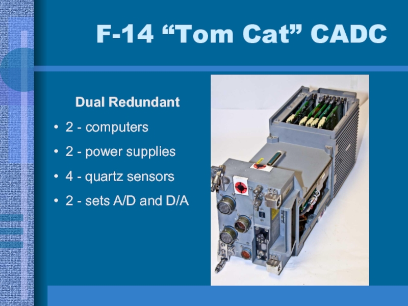
F-14 “Tom Cat” CADC Dual Redundant 2 - computers 2 - power supplies 4 - quartz
Содержание
- 1. F-14 “Tom Cat” CADC Dual Redundant 2 - computers 2 - power supplies 4 - quartz
- 2. Computer (CADC) Design ConstraintsSize: 40 sq inches
- 3. F-14 In-FlightThree minute YouTube Video
- 4. What Is A C.A.D.C.?A Flight Computer to:compute
- 5. A Flight Computer to:compute and control wing
- 6. A Flight Computer to:provide other critical flight
- 7. State-of-the-Art in 1968?The TechnologyTTL Bipolar -
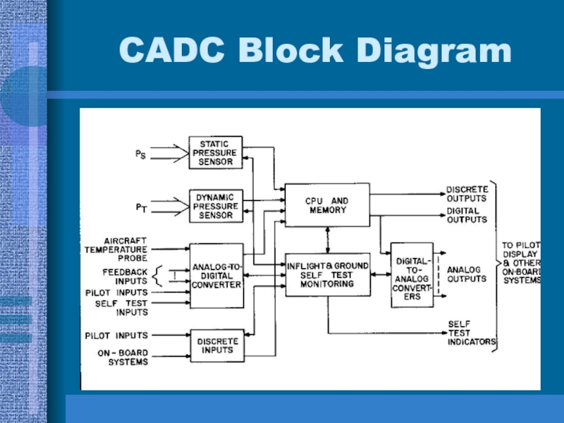
- 8. CADC Block Diagram
- 9. Microprocessor Self Test FunctionsIn-Flight Diagnostics 100% of
- 10. Required Arithmetic Calculations 6th Order Polynomials F(x)
- 11. Microprocessor Data StructureNumber Systemfractional fixed point computationtwo’s
- 12. Microprocessor Technologyhigh level of integration - P
- 13. Microprocessor Design Decisionsserial instruction and data transferdistributive
- 14. Microprocessor F-14 System Diagram
- 15. Microprocessor System Timing375Khz Clock, 2.66 us bit
- 16. Microprocessor Functional UnitsParallel Multiplier Unit (PMU)Parallel Divider
- 17. Computational Requirements
- 18. Microprocessor Chip Set PMU Functions20-bit parallel multiplierthree
- 19. PMU
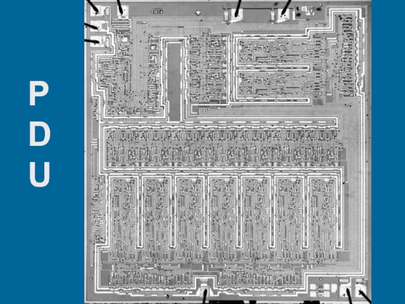
- 20. Microprocessor Chip Set PDU Functions20-bit parallel dividerthree
- 21. PDU
- 22. Microprocessor Chip Set CPU Functionslogical and arithmetic
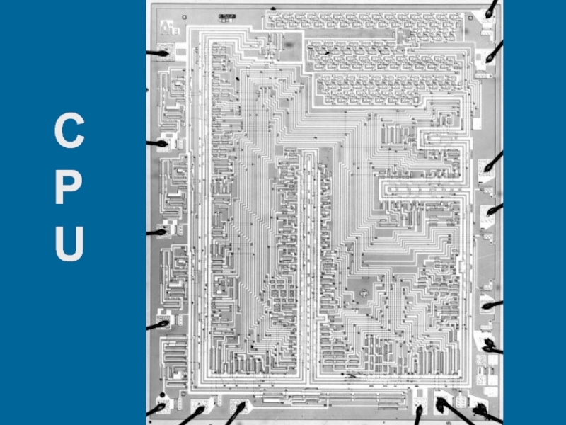
- 23. CPU
- 24. Microprocessor Chip Set SLU Functionsthree channel digital
- 25. SLU
- 26. Microprocessor Chip Set RAM Functionssixteen 20-bit static registersrandom access read-write storage53.3 μs I/O time5-bit instruction word
- 27. RAM
- 28. Microprocessor Chip Set ROM Functions2560-bit random access/sequential
- 29. ROM
- 30. Microprocessor Technology Spec’sCHIP DEVICES
- 31. PMUPDUCPUSLURAMROM
- 32. Microprocessor Instruction SetPMU - continuous - co-processorPDU
- 33. Microprocessor Equations - Angle of Attack
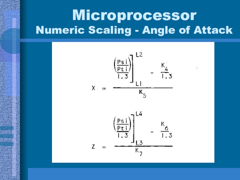
- 34. Microprocessor Numeric Scaling - Angle of Attack
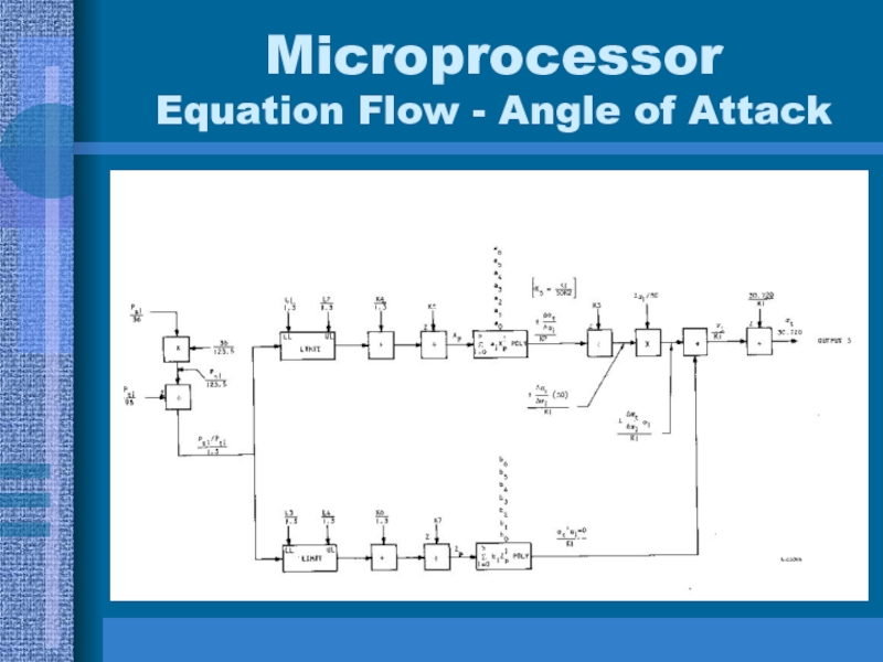
- 35. Microprocessor Equation Flow - Angle of Attack
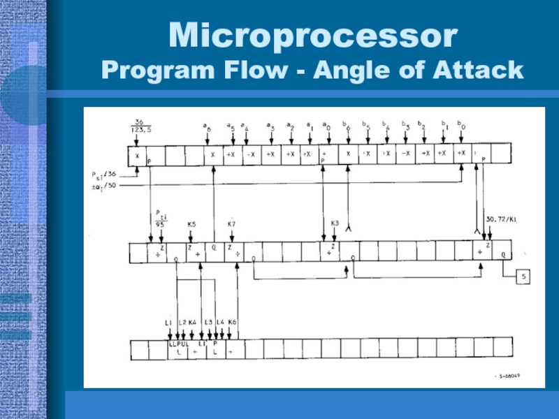
- 36. Microprocessor Program Flow - Angle of Attack
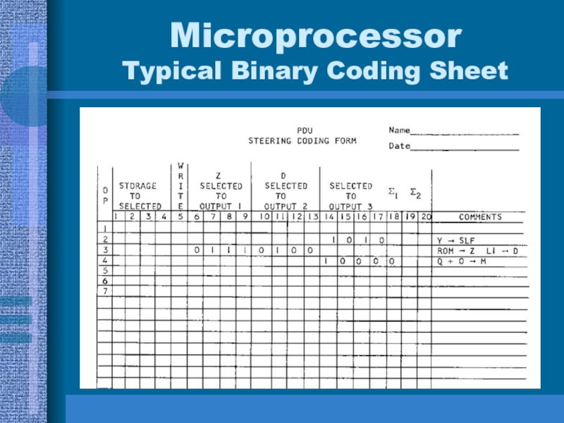
- 37. Microprocessor Typical Binary Coding Sheet
- 38. Microprocessor Initial Programming AidsNo assembler No compilerNo simulatorNo debuggerNo hardware prototype
- 39. Microprocessor Testing/Computer AidsFailure analysis simulation (circuit logic level
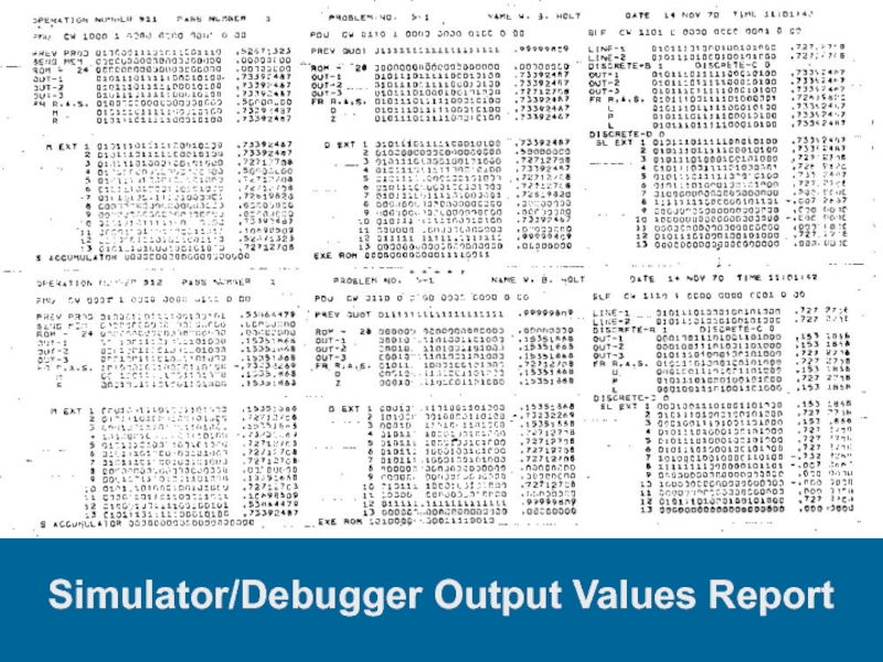
- 40. Simulator/Debugger Output Values Report
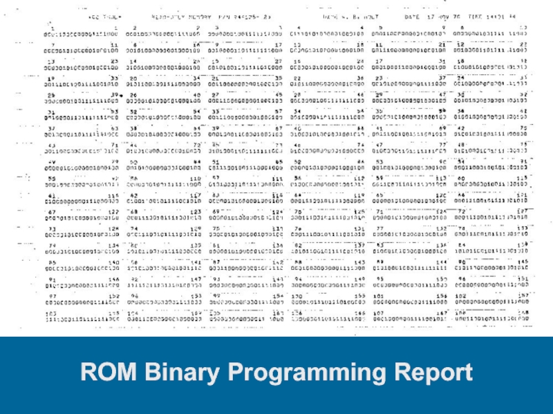
- 41. ROM Binary Programming Report
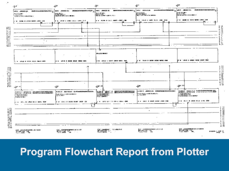
- 42. Program Flowchart Report from Plotter
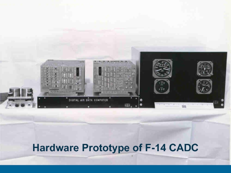
- 43. Hardware Prototype of F-14 CADC
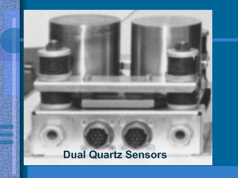
- 44. Dual Quartz Sensors
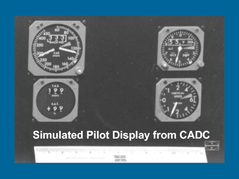
- 45. Simulated Pilot Display from CADC
- 46. General Design Accomplishments1st microprocessor chip set1st aerospace
- 47. Specific Design Accomplishments1st microprocessor with built-in programmed
- 48. Скачать презентанцию
Computer (CADC) Design ConstraintsSize: 40 sq inches for microprocessorPower: 10 wattsCost: $3,000-$5,000Temperature: -55 to +125 deg CProvide data for control & firing of 6 Phoenix / Sidewinder missiles at the same
Слайды и текст этой презентации
Слайд 2Computer (CADC)
Design Constraints
Size: 40 sq inches for microprocessor
Power: 10 watts
Cost:
$3,000-$5,000
Temperature: -55 to +125 deg C
Provide data for control &
firing of 6 Phoenix / Sidewinder missiles at the same timeOthers: Acceleration, mechanical shock, reliability, project schedule
Слайд 3F-14 In-Flight
Three minute YouTube Video
http://www.youtube.com/watch?v=yhyprrof0JM
Observe
the various positions of the wings. They are 100% computer
controlled.Observe the dynamic flow of air across the plane. The computer is constantly correcting for stability.
When there is a cloud formation around the plane it is breaking the sound barrier (the Danger Zone)
Слайд 4What Is A C.A.D.C.?
A Flight Computer to:
compute and display
altitude
air speed
vertical speed
mach number
temperature
Слайд 5A Flight Computer to:
compute and control
wing speed, position, and
rate
maneuver flap position
glove vane position
angle of attack
correctionСлайд 6A Flight Computer to:
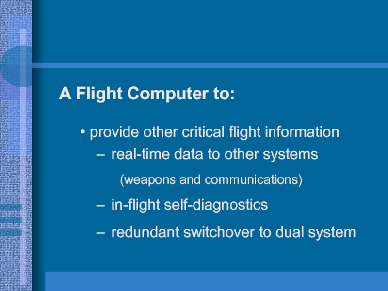
provide other critical flight information
real-time data
to other systems
(weapons and communications)
in-flight self-diagnostics
redundant switchover
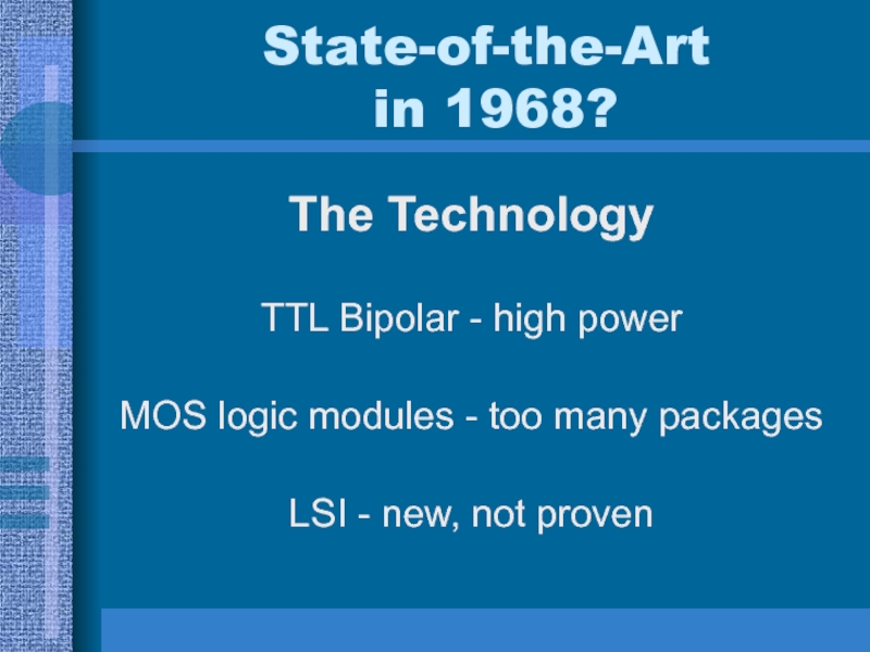
to dual systemСлайд 7State-of-the-Art
in 1968?
The Technology
TTL Bipolar - high power
MOS logic modules
- too many packages
LSI - new, not proven
Слайд 9Microprocessor
Self Test Functions
In-Flight Diagnostics
100% of all connections/data paths
100%
of all ROM bits
100% non-arithmetic circuits
98% all arithmetic
unit single failuresdual redundant system
pilot notification
Слайд 10Required
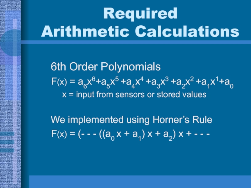
Arithmetic Calculations
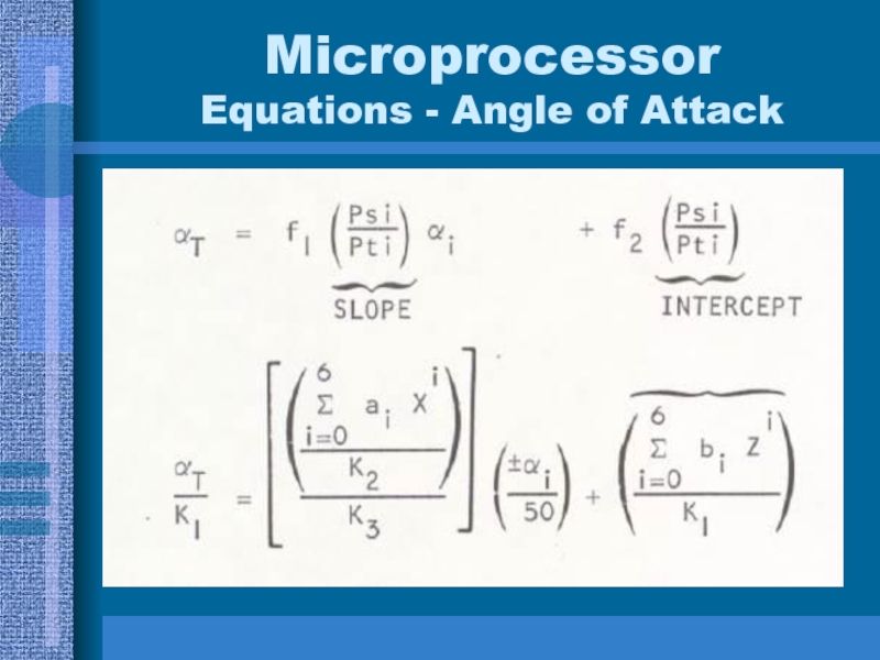
6th Order Polynomials
F(x) = a6x6+a5x5 +a4x4 +a3x3
+a2x2 +a1x1+a0
x = input from sensors or
stored valuesWe implemented using Horner’s Rule
F(x) = (- - - ((a0 x + a1) x + a2) x + - - -
Слайд 11Microprocessor
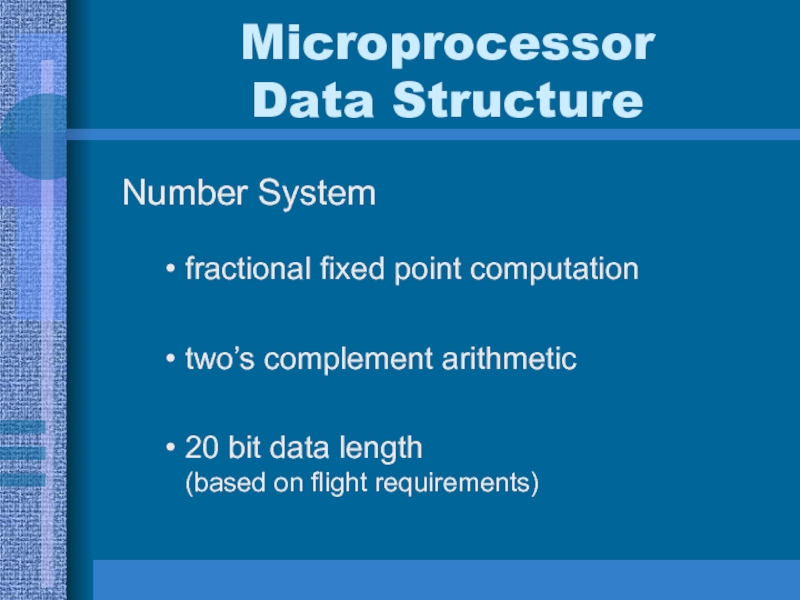
Data Structure
Number System
fractional fixed point computation
two’s complement arithmetic
20 bit data
length
(based on flight requirements)
Слайд 12Microprocessor
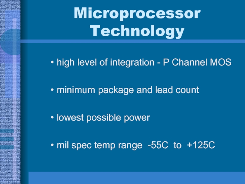
Technology
high level of integration - P Channel MOS
minimum package
and lead count
lowest possible power
mil spec temp range -55C
to +125CСлайд 13Microprocessor
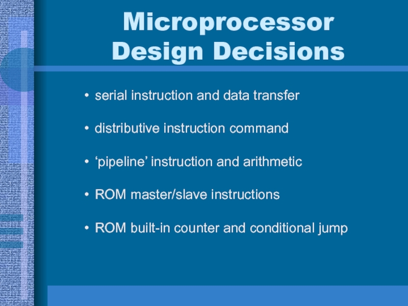
Design Decisions
serial instruction and data transfer
distributive instruction command
‘pipeline’ instruction and
arithmetic
ROM master/slave instructions
ROM built-in counter and conditional jump
Слайд 15Microprocessor
System Timing
375Khz Clock, 2.66 us bit time
One word = 20
bit times or 53.3 us
Operation time - two words
512
Op times - computational Cycle18.3 Cycles per second
9370 Op times per second for each
computational unit
Слайд 16Microprocessor
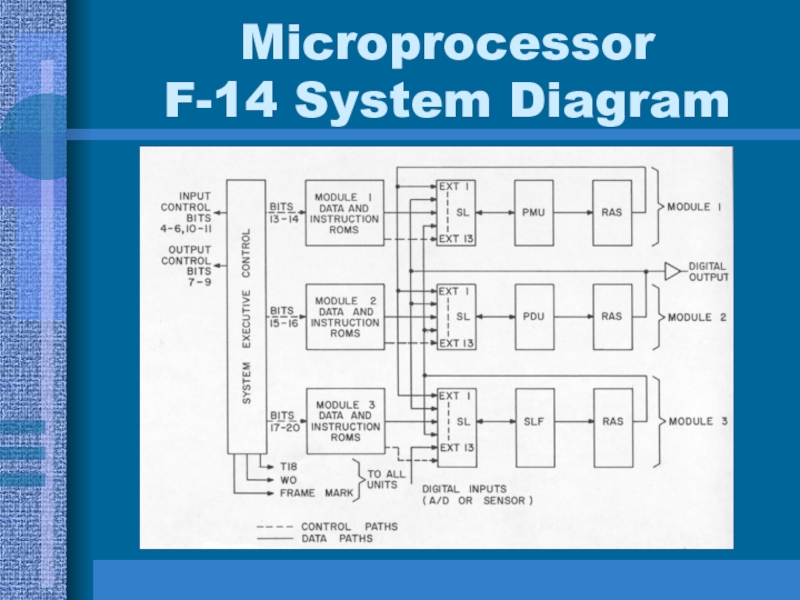
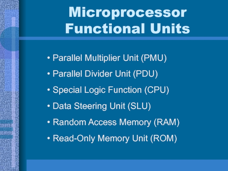
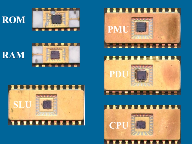
Functional Units
Parallel Multiplier Unit (PMU)
Parallel Divider Unit (PDU)
Special Logic Function
(CPU)
Data Steering Unit (SLU)
Random Access Memory (RAM)
Read-Only Memory Unit (ROM)
Слайд 17Computational Requirements
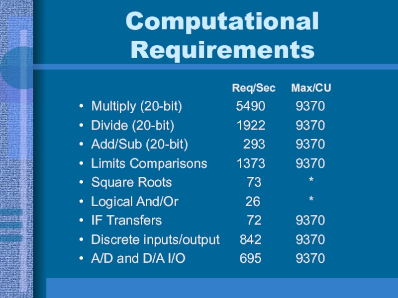
Req/Sec Max/CU
Multiply (20-bit) 5490 9370
Divide (20-bit) 1922 9370
Add/Sub (20-bit) 293 9370
Limits Comparisons 1373 9370
Square Roots 73 *
Logical And/Or 26 *
IF Transfers 72 9370
Discrete inputs/output 842 9370
A/D and D/A I/O 695 9370
Слайд 18Microprocessor Chip Set PMU Functions
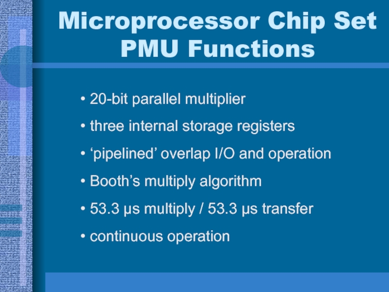
20-bit parallel multiplier
three internal storage registers
‘pipelined’
overlap I/O and operation
Booth’s multiply algorithm
53.3 μs multiply / 53.3
μs transfercontinuous operation
Слайд 20Microprocessor Chip Set PDU Functions
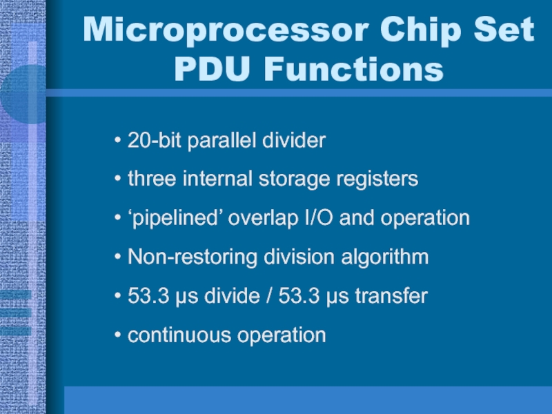
20-bit parallel divider
three internal storage registers
‘pipelined’
overlap I/O and operation
Non-restoring division algorithm
53.3 μs divide / 53.3
μs transfercontinuous operation
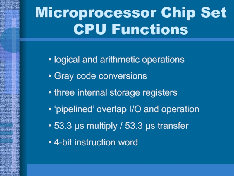
Слайд 22Microprocessor Chip Set CPU Functions
logical and arithmetic operations
Gray code conversions
three
internal storage registers
‘pipelined’ overlap I/O and operation
53.3 μs multiply /
53.3 μs transfer4-bit instruction word
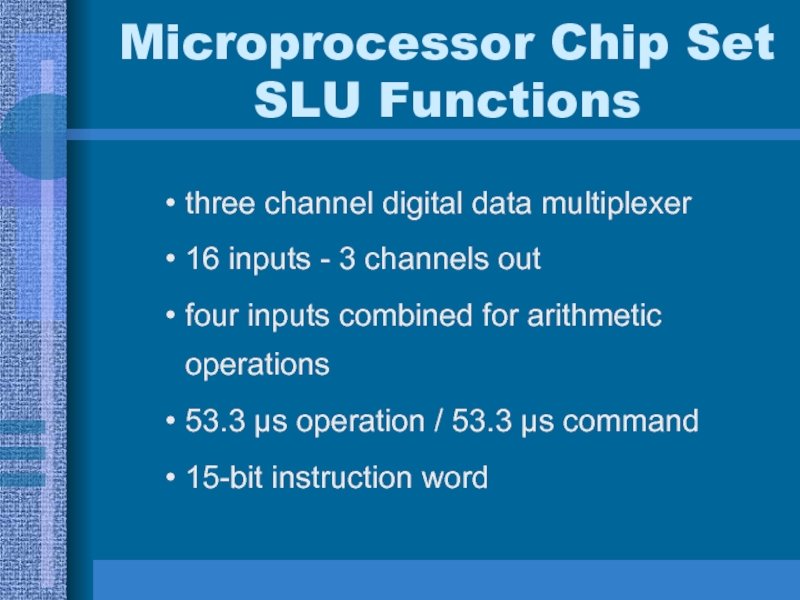
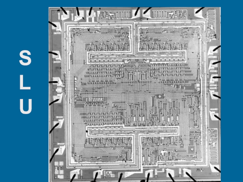
Слайд 24Microprocessor Chip Set SLU Functions
three channel digital data multiplexer
16 inputs
- 3 channels out
four inputs combined for arithmetic operations
53.3 μs
operation / 53.3 μs command15-bit instruction word
Слайд 26Microprocessor Chip Set RAM Functions
sixteen 20-bit static registers
random access read-write
storage
53.3 μs I/O time
5-bit instruction word
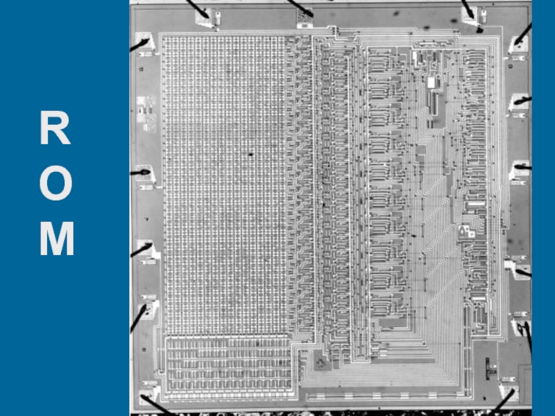
Слайд 28Microprocessor Chip Set ROM Functions
2560-bit random access/sequential access fixed memory
- 128 words x 20-bits
can parallel eight ROM’s for 1024
wordsprogram counter - cleared / +- increment / hold / external
data out / parity out
20-bit instruction word
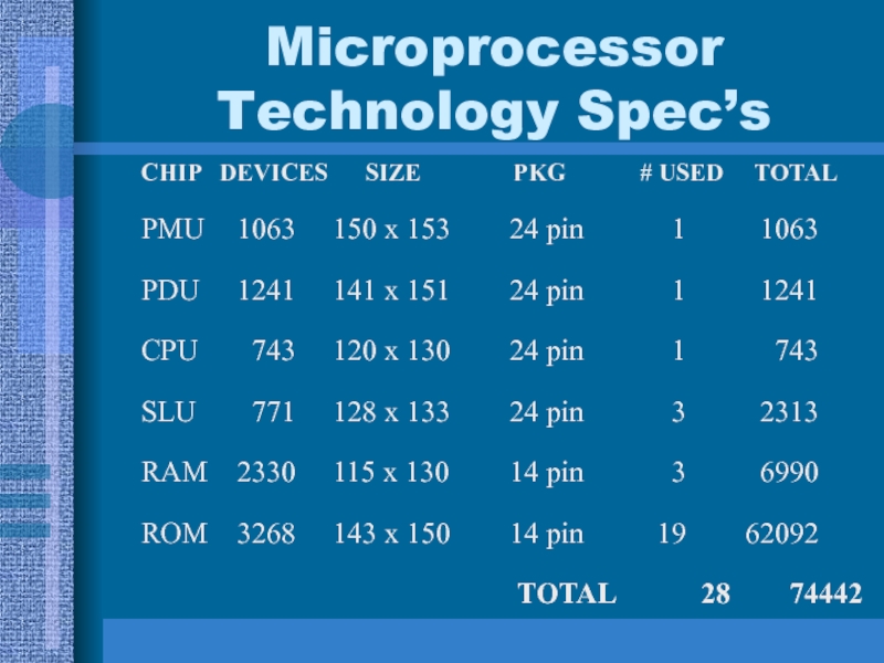
Слайд 30Microprocessor Technology Spec’s
CHIP DEVICES SIZE
PKG
# USED TOTALPMU 1063 150 x 153 24 pin 1 1063
PDU 1241 141 x 151 24 pin 1 1241
CPU 743 120 x 130 24 pin 1 743
SLU 771 128 x 133 24 pin 3 2313
RAM 2330 115 x 130 14 pin 3 6990
ROM 3268 143 x 150 14 pin 19 62092
TOTAL 28 74442
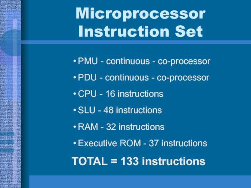
Слайд 32Microprocessor
Instruction Set
PMU - continuous - co-processor
PDU - continuous - co-processor
CPU
- 16 instructions
SLU - 48 instructions
RAM - 32 instructions
Executive ROM
- 37 instructionsTOTAL = 133 instructions
Слайд 38Microprocessor
Initial Programming Aids
No assembler
No compiler
No simulator
No debugger
No hardware prototype
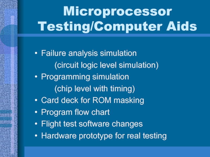
Слайд 39Microprocessor
Testing/Computer Aids
Failure analysis simulation
(circuit logic level simulation)
Programming simulation
(chip level
with timing)
Card deck for ROM masking
Program flow chart
Flight test software
changesHardware prototype for real testing
Слайд 46General Design Accomplishments
1st microprocessor chip set
1st aerospace microprocessor
1st fly-by-wire flight
computer
1st military microprocessor
1st production microprocessor
1st fully integrated chip set microprocessor
1st
20-bit microprocessorСлайд 47Specific Design Accomplishments
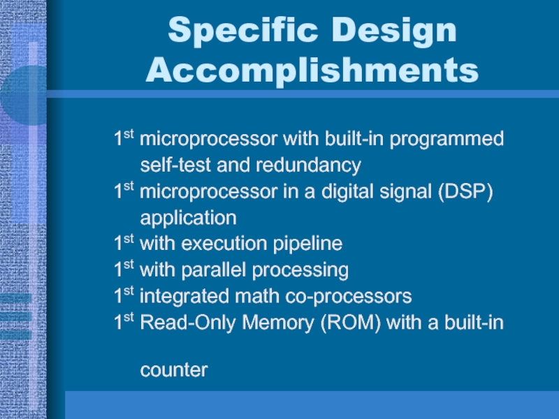
1st microprocessor with built-in programmed
self-test and redundancy
1st microprocessor in a digital signal (DSP)
application1st with execution pipeline
1st with parallel processing
1st integrated math co-processors
1st Read-Only Memory (ROM) with a built-in
counter
