Разделы презентаций
- Разное
- Английский язык
- Астрономия
- Алгебра
- Биология
- География
- Геометрия
- Детские презентации
- Информатика
- История
- Литература
- Математика
- Медицина
- Менеджмент
- Музыка
- МХК
- Немецкий язык
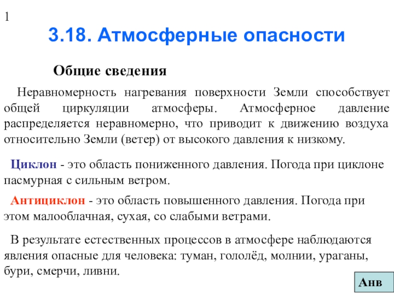
- ОБЖ
- Обществознание
- Окружающий мир
- Педагогика
- Русский язык
- Технология
- Физика
- Философия
- Химия
- Шаблоны, картинки для презентаций
- Экология
- Экономика
- Юриспруденция
Lecture 2 – Field Effect Transistors (FET):
Содержание
- 1. Lecture 2 – Field Effect Transistors (FET):
- 2. Compare Bipolar to FET:2. Bipolar transistors use
- 3. N-Channel FET: 1. An N-channel FET is
- 4. N-Channel FET Bias: Figure 1 is the
- 5. N-Channel FET GraphsFigure 4 shows the output
- 6. P-Channel FET: 1. An P-channel FET is
- 7. N-Channel FET Example: Given this circuit, With
- 8. N-Channel MOSFET: 1. An N-channel MOSFET is
- 9. N-Channel MOSFET Bias: Figure 6 is the
- 10. N-Channel MOSFET Example: Given this circuit, With
- 11. MOSFET NOT Gate: Given this circuit, with
- 12. MOSFET NAND Gate: Given this circuit, with
- 13. MOSFET NOR Gate: Given this circuit, with
- 14. Скачать презентанцию
Compare Bipolar to FET:2. Bipolar transistors use the input current (Ib) to make the output current. FETs use the input voltage (Vg) to make the output current. 1. FETs are also
Слайды и текст этой презентации
: By Karl LebkuchnerSuleyman Demirel UniversityJanuary 2013")
Слайд 2Compare Bipolar to FET:
2. Bipolar transistors use the input current
(Ib) to make the output current. FETs use the input
voltage (Vg) to make the output current.1. FETs are also made of N type and P-type semiconductors.
3. FETs usually have a much higher input impedance than bipolar transistors.
4. Usually, FET input voltages do not control the output current as exactly as bipolar input currents control the output current.
: Compare Bipolar to FET:2. Bipolar transistors use the input current (Ib)")
Слайд 3N-Channel FET:
1. An N-channel FET is made with an
N-type semiconductor that has two smaller P-type semiconductors put on
the sides. The P-type is called the Gate, one side of the N-type is called the Drain and the other is the Source.2. FETs work on the idea of an electric field. As the voltage on the gate (P-type) changes, then the reverse bias of the PN Junctions change. This reverse bias makes an electric field called the depletion region. This depletion region will open the N-type channel or close it for current.
: N-Channel FET: 1. An N-channel FET is made with an N-type")
Слайд 4N-Channel FET Bias:
Figure 1 is the symbol for the
N-Channel FET
· The N-channel FET should be biased as in Figure
2. The positive terminal of the drain to source supply connected to the Drain (negative to source). · The gate to source voltage (Vgs) will control the drain to source (Id) current. Vgs should be 0V or negative.
· The equation for the Drain current of the FET is:
Id = Idss ( 1 – Vgs / Vp) 2 where Idss = the maximum (or saturation drain current) and Vp = maximum gate voltage
· For circuits: use Ig = 0 and Id = Is (Idrain = Isource)
: N-Channel FET Bias: Figure 1 is the symbol for the N-Channel")
Слайд 5N-Channel FET Graphs
Figure 4 shows the output graph for the
FET. The red line is for pinchoff (Vgs = -4
= Vp). Here, the N-channel in the FET is smallest and Id=0A.The blue section in Figure4 is called the ohmic region. Here is the N-channel has a changing resistance.
In Figure4, the section to the right of the blue, shows the saturation region, where Id = Idss and is maximum.
Figure3 shows the parabolic graph for how Vgs makes Id.
: N-Channel FET GraphsFigure 4 shows the output graph for the FET.")
Слайд 6P-Channel FET:
1. An P-channel FET is made with an
P-type semiconductor that has two smaller N-type semiconductors put on
the sides. The N-type is called the Gate, one side of the P-type is called the Drain and the other is the Source.2. The P-channel FET has a positive Vgs. The Drain is connected to the negative side of a power supply. So the drain current goes in the source and out of the drain.
: P-Channel FET: 1. An P-channel FET is made with an P-type")
Слайд 7N-Channel FET Example:
Given this circuit, With with Va =
-2.5V, R1= 10K,
Vb = 10V, R2= 2K,
Idss=10mA and Vp=-5V. What are the currents Ig, Id and Is? What is Vds? Id = Idss ( 1 – Vgs / Vp)2 = 10mA (1 - -2.5V/ -5V) 2 =2.5mA
Is = Id = 2.5mA
Vds = Vb – R2 x Id = 10V – 2K x 2.5mA = 5V
Starting with
Ig = 0
: N-Channel FET Example: Given this circuit, With with Va = -2.5V,")
Слайд 8N-Channel MOSFET:
1. An N-channel MOSFET is made with a
P-type semiconductor base that has a smaller N-type semiconductor put
in one side (Source and Drain). On top of this is put an oxide insulation. Then a metal called the Gate.2. MOSFETs also work on the idea of an electric field. As the gate voltage becomes more negative, it will push electrons in the channel to go into the P-type and be combined with holes. So the Drain current will be less. The Gate voltage will open the N-type channel or close it for current Id.
N-Type
channel
: N-Channel MOSFET: 1. An N-channel MOSFET is made with a P-type")
Слайд 9N-Channel MOSFET Bias:
Figure 6 is the symbol for the
N-Channel MOSFET
· The N-channel MOSFET should be biased as in Figure
7. The positive terminal of the drain to source supply connected to the Drain. · The gate to source voltage (Vgs) will control the drain to source (Id) current. For depletion mode, Vgs should be 0V or negative. For enhancement mode, Vgs is >0.
· The equation for the Drain current of the MOSFET is:
Id = Idss ( 1 – Vgs / Vp) 2 where
Idss = the saturation drain current.
Vp = maximum gate voltage
Drain
Figure6
Source
Gate
: N-Channel MOSFET Bias: Figure 6 is the symbol for the N-Channel")
Слайд 10N-Channel MOSFET Example:
Given this circuit, With with Vc =
10V, R1= 1M,
R2= 2K, R3= 1K , Vp= -4V
and Idss=4mA. What are the currents Ig and Id? For a MOSFET Ig=0A, so Vr1 =0V and Vgs = -Vr3 = -IdxR3.
Next make a graph for the MOSFET: using Vgs=Vp/2 = -2V then Id=Idss/4=1mA, when Vgs=Vp then Id=0, when Vgs=0 then Id=Idss
Now for the circuit: When Id=0 then Vgs=0,
When Vgs= -3V, then Id = -Vgs/ R3 = - -3V/ 1K = 3mA. So draw a line.
Where the lines meet: Id = 1.5mA
: N-Channel MOSFET Example: Given this circuit, With with Vc = 10V,")
Слайд 11MOSFET NOT Gate:
Given this circuit, with Vcc = 5V.
The MOSFETs will act like switches (ON or OFF).
With
the source of a P –channel MOSFET connected to Vcc.The source of the N –channel MOSFET is connected to Ground (0V).
When Vin=0V, then for the N-channel, Vgs=0V so it is OFF. But for the P-channel Vgs= -5V so it is ON. So Vout = Vcc.
When Vin=5V, then for the N-channel, Vgs=5V so it is ON. But for the P-channel Vgs= 0V so it is OFF. So Vout = 0V.
Pchannel
: MOSFET NOT Gate: Given this circuit, with Vcc = 5V. The")
Слайд 12MOSFET NAND Gate:
Given this circuit, with Vcc = 5V.
The MOSFETs will act like switches (ON or OFF).
Vout
: MOSFET NAND Gate: Given this circuit, with Vcc = 5V. The")
Слайд 13MOSFET NOR Gate:
Given this circuit, with Vcc = 5V.
The MOSFETs will act like switches (ON or OFF).
: MOSFET NOR Gate: Given this circuit, with Vcc = 5V. The")